𐄀 Связь технологий с будущим


Электрическая принципиальная схема
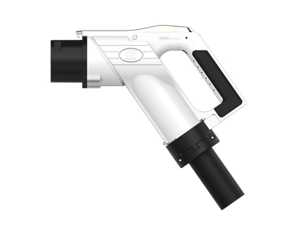
Подробная информация о модели разъема постоянного тока YG 762 (эта спецификация относится к модели в следующей таблице): | |||||||||||
Нет. | Имя | Спецификация проводки порта (мм²) | |||||||||
Постоянный ток | ДК- | ПЭ | А | А- | СС1 | СС2 | С | С- | |||
1 | YGC762-EV-P9P-80 штекер | 20 | 20 | 25 | 4 | 4 | 0,75 | 0,75 | 0,75 | 0,75 | |
2 | YGC762-EV-P9P-125 штекер | 35 | 35 | 25 | 4 | 4 | 0,75 | 0,75 | 0,75 | 0,75 | |
3 | YGC762-EV-P9P-160 штекер | 50 | 50 | 25 | 4 | 4 | 0,75 | 0,75 | 0,75 | 0,75 | |
4 | YGC762-EV-P9P-200 штекер | 70 | 70 | 25 | 4 | 4 | 0,75 | 0,75 | 0,75 | 0,75 | |
5 | YGC762-EV-P9P-250 штекер | 80 | 80 | 25 | 4 | 4 | 0,75 | 0,75 | 0,75 | 0,75 | |
6 | YGC762A-EV-P9P-125 штекер | 35 | 35 | 25 | 4 | 4 | 0,75 | 0,75 | 0,75 | 0,75 | |
7 | YGC762A-EV-P9P-160 штекер | 50 | 50 | 25 | 4 | 4 | 0,75 | 0,75 | 0,75 | 0,75 | |
8 | YGC762A-EV-P9P-200 штекер | 70 | 70 | 25 | 4 | 4 | 0,75 | 0,75 | 0,75 | 0,75 | |
9 | YGC762A-EV-P9P-250 штекер (УЗИ 250 А) | 70 | 70 | 25 | 4 | 4 | 0,75 | 0,75 | 0,75 | 0,75 | |
10 | YGC762A-EV-P9P-250 штекер | 80 | 80 | 25 | 4 | 4 | 0,75 | 0,75 | 0,75 | 0,75 | |
Адаптирующий кабель | |||||||||||
Нет. | Спецификации катиона | Адаптировать спецификации кабеля | Номер сердечника кабеля | OD (мм) | |||||||
1 | 80А | ТПЭ 2x20мм2 25мм2 2x4мм2 2xP (2x0.75мм2) P (6x0.75мм2) | 15 | Φ 32 ± 1 | |||||||
2 | 125А | ТПЭ 2x 35 мм2 25 мм2 2x4 мм2 2xP (2x0,75 мм2) P(6x0,75 мм2) | 15 | Φ 36 ± 1 | |||||||
3 | 160А | ТПЭ 2x50mm2 25mm2 2x4mm2 2xP(2x0.75mm2) P(6x0.75mm2) | 15 | Φ 36,5 ± 1 | |||||||
4 | 200А | ТПЭ 2x70мм2 25 мм2 2x4мм2 2xP (2x0.75мм2) P (6x0.75мм2) | 15 | Φ 40 ± 1 | |||||||
5 | 250А | TPE 2x 80 мм2 25 мм2 2x4 мм2 2xP (2x0,75 мм2) P(6x0,75 мм2) | 15 | Φ 40 ± 1 | |||||||
6 | 80А | ТПЭ 2x20мм2 25мм2 2x4мм2 2xP (2x0.75мм2) P (7x0.75мм2) | 16 | Φ 32 ± 1 | |||||||
7 | 125А | ТПЭ 2x 35 мм2 25 мм2 2x4 мм2 2xP (2x0,75 мм2) P(7x0,75 мм2) | 16 | Φ 36 ± 1 | |||||||
8 | 160А | TPE 2x50mm2 25mm2 2x4mm2 2xP(2x0.75mm2) P(7x0.75mm2) | 16 | ||||||||
9 | 200А | ТПЭ 2x70мм2 25мм2 2x4мм2 2xP (2x0.75мм2) P (7x0.75мм2) | 16 | Φ 40 ± 1 | |||||||
10 | 250А (ультразвуковая заварка) | TPE 2x 70 мм2 25 мм2 2x4 мм2 2xP (2x0,75 мм2) P(7x0,75 мм2) | 16 | Φ 40 ± 1 | |||||||
11 | 250А | TPE 2x 80 мм2 25 мм2 2x4 мм2 2xP (2x0,75 мм2) P(7x0,75 мм2) | 16 | Φ 40 ± 1 | |||||||
Внимание | |||||||||||
★Выше приведена общая модель продукта, проводка, пожалуйста, выберите в соответствии с требованиями к диаметру линии, если есть какие-либо индивидуальные требования, проконсультируйтесь с нашей компанией; ★Жгут проводов для индивидуальных продуктов должен быть конкретными моделями в соответствии с фактическим применением, обратитесь к нашей компании за подробностями. | |||||||||||
Электрические параметры | Определение порта | Постоянный ток ± | ПЭ | А ± | СС1 | СС2 | С ± | ||||
Спецификация проводки (единица измерения: Мм2) | 25 | 35 | 70 | 70 | 80 | 25 | 0,75 ~ 4 | 0,75 | 0,75 | 0,75 | |
Диаметр контактного терминала (Мм) | Φ12 | Φ6 | Φ3 | Φ3 | Φ3 | Φ3 | |||||
Номинальное рабочее напряжение (ДК) | 750V/1000V | / | 0 ~ 30 В | 0 ~ 30 В | 0 ~ 30 В | 0 ~ 30 В | |||||
Номинальный рабочий ток (ДК) | 80А | 125А | 200А | 250А | 250А | / | 2 ~ 20А | 2А | 2А | 2А | |
Контактное сопротивление | ≤ 0,3 мОм | ≤ 0,4 мОм | ≤ 3 мОм | ||||||||
Сопротивление изоляции | ≥ 2000 МОм (1000 В переменного тока) | ||||||||||
Выдерживаемое давление (50 Гц, Нормальный переменный ток) | Проверка проводки после подключения: ① Напряжение сопротивления между DC и DC-3500V AC 1 мин; ② DC , DC-и PE, S , S , A , A-сопротивление напряжения 1500 В переменного тока 1 мин; ③ PE и S , S-, A , A-соответственно устойчивое напряжение 1500 В переменного тока 1 мин; ④ S , S-, CC1, A, А-два сопротивления напряжением 1500 В переменного тока 1 мин; Тест после сокета iПроводной s: ① Напряжение сопротивления между DC и DC-3500V AC 1 мин; ② DC , DC-и PE, S , S-, CC1, CC2, A-сопротивление напряжения 1500V AC 1 мин; ③ PE и S , S-, CC2, A , A-сопротивление напряжения 1500V AC 1 мин; ④ S , S-, CC2, CC1, A , A-два взаимных сопротивления напряжения 1500 В переменного тока 1 мин. | ||||||||||
Механические параметры производительности | Срок службы: | 10000 раз | |||||||||
| Сила вставки: | <140Н | ||||||||||
| Блокировка-в силу: | 200Н | ||||||||||
Параметры экологической эффективности | Перед вставкой: | YG 762 / YG762A IP54; | |||||||||
| После вставки: | YG 762 / YG762A IP55; YG762A Электрическая часть может достигать IP67 (за исключением интерфейса подключения к розетке). | ||||||||||
| Примечание: | Избегайте радиуса изгиба хвостовой проводки <6 наружного диаметра кабеля | ||||||||||
| Температура окружающей среды: | -30 ℃ ~ 50 ℃ | ||||||||||
Материал | Приложение: | Инженерные пластмассы (высокопроизводительный ПК) | |||||||||
| Терминал: | Медь, поверхностный покрытый серебр/никель | ||||||||||
| Части уплотнения: | Силиконовая резина или эластичный изоляционный материал | ||||||||||
| Ранг Плам-ретардант: | UL94 V-0 | ||||||||||
Стандарты внедрения | GB / T 18487,1-2015 EV-Часть 1: | Общие требования | |||||||||
| Соединительные устройства GB / T 20234,1-2015 для проводной зарядки электромобилей-часть 1: | Общие требования | ||||||||||
| GB / T 20234,3-2015 Соединения для зарядки передачи электромобилей; Часть 3: | Интерфейс зарядки постоянного тока | ||||||||||
Электрический принцип | Определение функции каждого терминала: | ||||||||||
Нет. | Идентификация терминала | Определение функции | |||||||||
| 1 | Постоянный ток | Источник питания постоянного тока положительный, а источник питания постоянного тока подключен к катоду аккумулятора. | |||||||||
| 2 | ДК- | Мощность постоянного тока отрицательная, подключите питание постоянного тока отрицательное, а батарея отрицательная | |||||||||
| 3 | ПЭ | Защитное заземление (PE), подключение к заземляющему проводу оборудования источника питания и заземляющему проводу кузова автомобиля | |||||||||
С | Связь для зарядки CAN _ H, соединяющая линию связи между небортовым зарядным устройством и электромобилем | ||||||||||
| 5 | С- | Связь для зарядки CAN _ L, соединяющая линию связи между небортовым зарядным устройством и электромобилем | |||||||||
| 6 | СС1 | Подтверждение подключения зарядки 1 | |||||||||
| 7 | СС2 | Подтверждение подключения зарядки 2 | |||||||||
| 8 | А | Вспомогательный источник питания низкого напряжения подключается к вспомогательному источнику питания низкого напряжения, обеспечиваемым не бортовым зарядным устройством для электромобилей. | |||||||||
| 9 | А- | Вспомогательный источник питания низкого напряжения отрицательный, подключен к вспомогательному источнику питания низкого напряжения, обеспечиваемым не бортовым зарядным устройством для электромобилей. | |||||||||
| 10 | Т1 | Датчик температуры положительный на правой стороне источника питания постоянного тока. | |||||||||
| 11 | Т1- | Датчик температуры со стороны постоянного тока отрицательный | |||||||||
| 12 | Т2 | Датчик температуры с отрицательной стороны источника питания постоянного тока положительный | |||||||||
| 13 | Т2- | Датчик температуры отрицательный на отрицательной стороне | |||||||||
★T1-and T2-are доступно | |||||||||||
| 14 | Электронный замок на 12V | Электронный замок в разъеме автомобиля положительный | |||||||||
| 15 | Электронный замок GND | Электронный замок внутри разъема автомобиля | |||||||||
| 16 | Электронный замок обратной связи ЗНАК | Электронный замок в разъеме автомобиля работает (разблокировка/блокировка) и обратная связь положительная | |||||||||
| 17 | Электронный замок обратной связи ЗНАК- | Электронный замок в разъеме автомобиля работает (разблокировка/блокировка) и обратная связь отрицательная | |||||||||
★Электронный замок GND и обратная связь с электронным замком SIGN-availabl | |||||||||||
Аксессуары для автомобильного разъема | 1. YG762 Защитная крышка штекера в сборе (опционально): | ||||||||||
 | |||||||||||
★Модель: YG 762-01-02-00 (112980000706) на заказ в соответствии с требованиями, соотношение заказа 1:1 (вилка: YG 762 защитная крышка заглушки в сборе). | |||||||||||
2. Сборка электромагнитного замка YG 762 (требуется): | |||||||||||
YG 762 (нормально открытый и нормально закрытый) YG 762-01-01-00 (112980000700 закрыто) YG 762-01-01-00 / 01 (112980001628 регулярный открытый) | Y G762A Электронный замок пистолета (нормально открытый и Нормально закрытый) 501021703907 (Электронный замок двигателя) 501021703906 (замок мотора) | ||||||||||
 |  | ||||||||||
★Модель: заказ по требованию, соотношение заказа 1:1 (вилка: компонент электромагнитного замка). | |||||||||||
3. Сборка платы управления PCBA (опционально): | |||||||||||
 | |||||||||||
★Модель: заказ по требованию, соотношение заказа 1:1 (штекер: сборка платы управления PCBA) YG762-01-12-00(112980001149) 0,4 м YG762-01-12-00/01(112980002602) 1,5 м YG762-01-12-00/02(111009802061) Полоса 1,5 м | |||||||||||
4. Датчик температуры (обязательно): | |||||||||||
| A) Датчик температуры PT1000 (Φ 3010 мм) (501021701034) Таблица размеров сопротивления:
Коэффициент коррекции температуры: 7 ℃ (фактическая температура клеммы = температура датчика 7 ℃) | |||||||||||
Б) Таблица сопротивления датчика температуры НТК 10 К 3950 (501021702315) габаритная:
Коэффициент коррекции температуры: 7 ℃ (фактическая температура клеммы = температура датчика 7 ℃) | |||||||||||
К) НТК 3435 10 КΩ (501021701772) | |||||||||||
D) Таблица сопротивления переключателя температуры (90 ± 5 ℃) (501021701036) | |||||||||||
E) Переключатель температуры (100 ± 5 ℃) (501021702297) | |||||||||||
★Штекер выбирает два датчика или температурных переключателя в DC / DC-согласно стандарту. | |||||||||||
5. Пустое сиденье (опция): | |||||||||||
YG349-02-00-00KR |
YG762-50-00-00KR | ||||||||||
★Модель: YG 349-02-00-00 КР (112980000394) YG 762-50-00-00 КР (111000500836) ★Выберите в соответствии с требованиями и сопоставьте заказ вилки, соотношение заказа 1:1 (вилка: пустое место) ★По требованию хвостовая линия может быть подключена к разъему; | |||||||||||
| 6. YG762A. Простой рычаг аварийного отпирания (опция): | |||||||||||
 | |||||||||||
★Модель: YG762 Простой стержень для аварийной разблокировки (114039803419) ★Согласно требованию, и заказ с штепсельной вилкой, поручая место кучи согласно реальной ситуации. | |||||||||||
Объявление информации | Пояснить: ★Логотип объявления соответствует таблице моделей "name" ★Примечание: о розетке штекерного типа нет объявления, наша компания будет увеличиваться в зависимости от реальной ситуации. | ||||||||||
Объявление логотипа | Устройство контроля температуры | Электромаг Замок Netic Устройство | Сильная проверка Номер отчета | Номер отчета CQC | |||||||
YGC762-EV-P9P-80 | Есть | Есть | QA16EE1EB4141 КА16ЭГ1ЭБ4141 | QA16XX1EFC341 | |||||||
YGC762-EV-P9P-125 | Есть | Есть | QA16EE1EB4141 КА16ЭГ1ЭБ4141 | QA16XX1EFC341 | |||||||
YGC762-EV-P9P-200 | Есть | Есть | QA16EE1EB4141 КА16ЭГ1ЭБ4141 | QA16XX1EFC341 | |||||||
YGC762-EV-P9P-250 | Есть | Есть | QA16EE1EB4141 КА16ЭГ1ЭБ4141 | QA16XX1EFC341 | |||||||
YGC762A-EV-P9P-80 | Есть | Есть | QA18EE1XZ5471 | К КК20029252191 | |||||||
YGC762A-EV-P9P-125 | Есть | Есть | QA18EE1XZ5471 | К КК20029252191 | |||||||
YGC762A-EV-P9P-200 | Есть | Есть | QA18EE1XZ5471 | К КК20029252191 | |||||||
YGC762A-EV-P9P-250 | Есть | Есть | QA18EE1XZ5471 | К КК20029252191 | |||||||
Запретить воздействие продуктов YG 762 на дождевую воду.
При использовании зарядного гнезда:
(1) КогдаАвтомобильный разъемВставлен и вставлен, проверьте, нет ли в отверстии патронов посторонних тел. Если после осмотра нет инородного тела
Метод Нормальные штепсельная вилка и тяга, контактируют изготовитель для обработки;
(2) При сообщении о неисправности изоляции сначала убедитесь, что сервисный выключатель аккумуляторной батареи отключен, и при необходимости закройте главный затвор системы цепи кузова автомобиля,
Проверьте, не протекает ли розетка, есть ли утечка воды, сначала протрите мультиметром, чтобы обнаружить изоляцию между клеммами.
Сопротивление (за исключением между PE и CC1), значение сопротивления 2000 МОм является нормальным, в противном случае свяжитесь с производителем для лечения;
(3) В случае ненормального зарядного соединения убедитесь, что служебный выключатель аккумулятора находится в отключенном состоянии, и при необходимости закройте систему контура тела.
Для общего затвора определите значение сопротивления между PE и CC1, если значение сопротивления составляет 1000 / -30 Ом, это нормально, в противном случае свяжитесь с
Обработка производителя;
(4) Регулярно протирайте и очищайте интерфейс зарядки спиртом, особенно металлический разъем внутри розетки.

Пошив разъемов под ваши уникальные потребности.
Обеспечение системных решений
Отвечайте на потребности в течение 12 часов


 Английский
  日本語
日本語  Deutsch
  ไทย
ไทย  русский
  العربية


")